Once you get your first OpenGL view working on an iPhone or iPad, one of the first things you’ll likely notice is that when you rotate your device, the rendered image in that view stretches during the animated rotation of the display. This post explains why this happens, and what you can do to deal with it. Example code can be found at https://github.com/codefromabove/OpenGLDeviceRotation.
The Problem
To demonstrate the issue I’m addressing here, I wrote about the simplest possible OpenGL iOS app: it just shows a square in the center of the screen. Here we have it in landscape and portrait orientations:
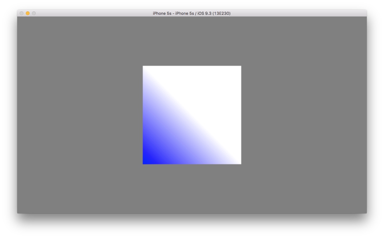
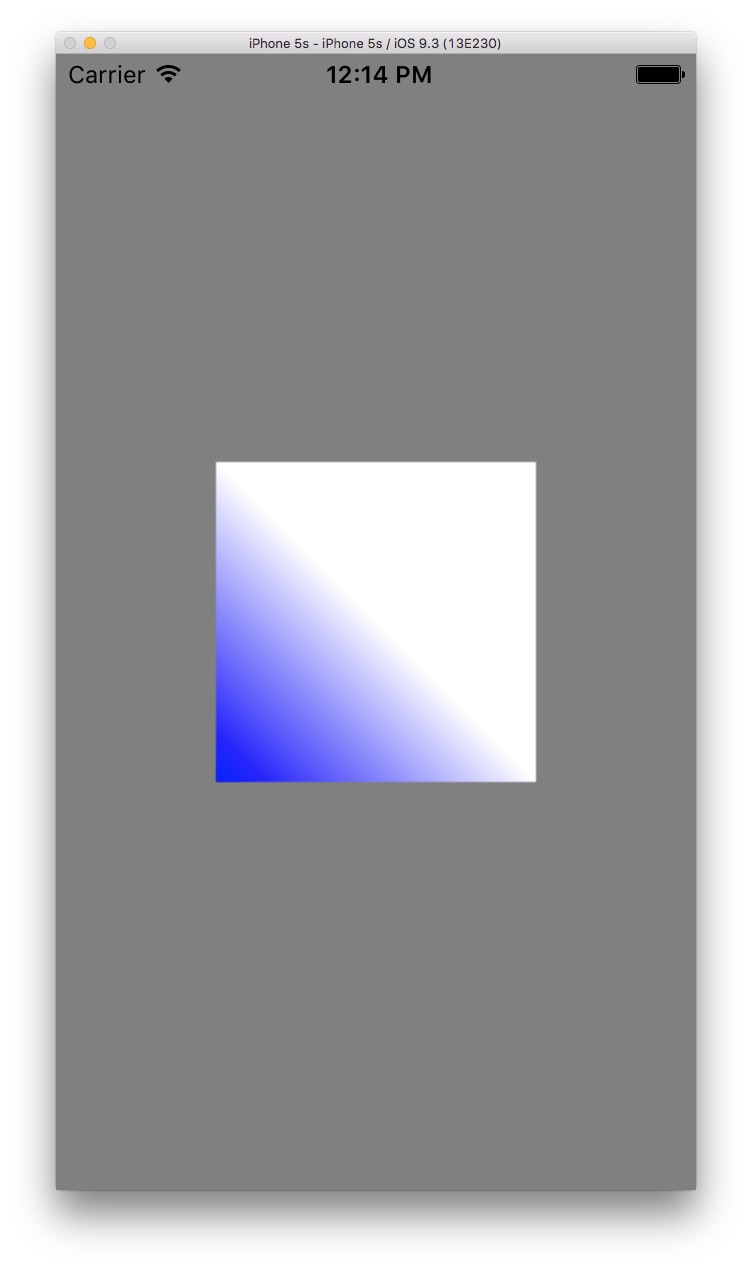
But what happens when we rotate the device? Here’s a screenshot movie of the Xcode simulator:
HQ Version: OpenGLBadOrientation
OpenGL View Basics
The “geometric” aspect of rendering consists of transforming triangle vertices in their local space to vertices in image space. Individual objects are defined in their own local coordinate spaces, and a transform takes them world space. From there, another transformation takes the vertices from world space to camera space. Finally, the vertices are transformed to 2D window coordinates by a viewport transform. This is shown in this figure:
![]()
In the sample code, I’ve opted to use an orthographic camera model, and am defining the sole object’s vertices in camera space, in order to keep the mathematics as simple as possible. In camera space, the camera is at the origin (0, 0, 0) and looks down the Z axis. The canonical orthographic viewing volume is a cube whose x, y, and z coordinates range from -1 to 1:
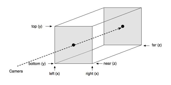
So, once the vertices are in camera space, the orthographic projection matrix transforms them into the canonical view volume’s (-1, 1) x (-1, 1) x (-1, 1) space. Since the orthographic view volume is simply an axis-aligned 3D box, the orthographic transform is typically constructed using some equivalent of the volume’s corners in camera space (right/left, top/bottom, near/far values). In the example app, I use this to create the orthographic projection matrix:
GLKMatrix4 GLKMatrix4MakeOrtho(float left,   float right,
                               float bottom, float top,
                               float nearZ,  float farZ)
{
    float ral = right + left;
    float rsl = right - left;
    float tab = top + bottom;
    float tsb = top - bottom;
    float fan = farZ + nearZ;
    float fsn = farZ - nearZ;

    GLKMatrix4 m = { 2.0 / rsl, 0.0, 0.0, 0.0,
                     0.0, 2.0 / tsb, 0.0, 0.0,
                     0.0, 0.0, -2.0 / fsn, 0.0,
                     -ral / rsl, -tab / tsb, -fan / fsn, 1.0 };
    return m;
}
Which creates this matrix:
=\begin{pmatrix}\frac{2}{r-l}&0&0&-\frac{r+l}{r-l}\\ 0&\frac{2}{t-b}&0&-\frac{t+b}{t-b}\\ 0&0&-\frac{2}{f-n} &-\frac{f+n}{f-n}\\ 0&0&0&1\end{pmatrix}")
So, ultimately, model vertices are transformed into points on the front plane of the view volume. Final transformation to points in the image is accomplished by the viewport transform. Since we’re transforming from a (-1, 1) x (-1, 1) plane to pixels in an image, the viewport transform is determined by the (image-space) rectangle, so an origin, width, and height are typically used:
 (\frac{width}{2})+x")
 (\frac{height}{2})+y")
=\begin{pmatrix}\frac{w}{2}&0&\frac{w}{2}+x\\ 0&\frac{h}{2}&\frac{h}{2}+y\\ 0&0&1\end{pmatrix}")
In general, one can render to a portion of the image space by specifying a viewport that doesn’t encompass the entire image space, but in the sample code, we simply use (0, 0) as the viewport’s origin, and the UIView’s dimensions as the viewport’s width and height.
The Naïve Approach
In the example code, our sole object is a square — a triangle strip of two triangles –centered about the origin and going from -0.5 to 0.5 in X and Y (we don’t have Z values, so a Z = 0 is implied).
GLfloat square[] = { -0.5, -0.5, 0.5, -0.5, -0.5,  0.5, 0.5,  0.5 };
glVertexAttribPointer([self vertexPositionLocation], 2, GL_FLOAT, GL_FALSE, 0, square);
glDrawArrays(GL_TRIANGLE_STRIP, 0, 4);
Our GL buffer has been created so that it fills the GLView (and hence the entire screen):
- (void)createBuffers
{
    GLuint renderbuffer;
    glGenRenderbuffers(1, &renderbuffer);
    [self setRenderBuffer:renderbuffer];
    glBindRenderbuffer(GL_RENDERBUFFER, renderbuffer);
    [[self context] renderbufferStorage:GL_RENDERBUFFER fromDrawable:(CAEAGLLayer *)[self view].layer];

    GLuint framebuffer;
    glGenFramebuffers(1, &framebuffer);
    [self setFrameBuffer:framebuffer];
    glBindFramebuffer(GL_FRAMEBUFFER, framebuffer);
    glFramebufferRenderbuffer(GL_FRAMEBUFFER, GL_COLOR_ATTACHMENT0, GL_RENDERBUFFER, renderbuffer);
}
I want the square to take up half the width of the screen in portrait mode, so I need to specify the projection matrix and viewport accordingly. I want the image to take up the entire GLView, so I set the viewport with origin (0, 0) and size equivalent to the view’s size in points. By setting the projection matrix left/right values to range from -1 to 1, the square will go from -0.5 to 0.5 in X. Because the GLView is not square, the projection matrix’s top/bottom values are set to the GLView’s width divided by the height:
- (void)render:(CADisplayLink *)displayLink
{
    GLView *glView = (GLView *)[self view];

    // Set the viewport
    glViewport(0, 0, [glView bounds].size.width, [glView bounds].size.height);

    // Compute the projection matrix
    GLKMatrix4 projectionMatrix;
    GLfloat    ratio = [glView bounds].size.width/[glView bounds].size.height;

    // Set the projection to match the dimensions of the GL view.
    if (ratio <= 1)
        projectionMatrix = GLKMatrix4MakeOrtho(-1, 1, -1/ratio, 1/ratio, 0, 100);
    else
        projectionMatrix = GLKMatrix4MakeOrtho(-ratio, ratio, -1, 1, 0, 100);
    ...
}
Note again that I’m simplifying greatly by mashing object, world, and camera spaces into a single space. With an iPhone 5s, we have a portrait-orientation view that is 320×568, whose aspect ratio is 0.563. This gives us:
- l = -1
- r = 1
- b = -1.775
- t = 1.775
- n = 0
- f = 100
If we take the first vertex (-0.5, -0.5, 0, 1) and transform it by our projection matrix, we have

If we apply the viewport transform to this camera-space vertex, we get:

If we apply the cumulative transforms to our square’s vertices, we get this in image space:

For landscape orientation, I want the square to be half the screen’s height, so I apply the same logic, with the X and Y directions reversing roles.
So, What’s the Problem?
I have code that draws the square as I want it to appear, for both device orientations. Now, what about rotating the device? Let’s look at the sequence of operations that happens when the user rotates the device, in terms of UIView functions that are called by the system, once the user has rotated the device past the threshold:
- …render…render…render
- viewWillTransitionToSize
- viewWillLayoutSubviews
- render…render…render…
By the time viewWillLayoutSubviews is called, the various UIViews have been resized to the size they will be in the new orientation, so typically one resizes one’s OpenGL render buffer to match the underlying view:
- (void)viewWillLayoutSubviews
{
    [super viewWillLayoutSubviews];

    // Delete the old buffer, and create a new one at the current size/orientation
    GLuint renderbuffer = [self renderBuffer];
    glDeleteRenderbuffers(1, &renderbuffer);

    glGenRenderbuffers(1, &renderbuffer);
    [self setRenderBuffer:renderbuffer];
    glBindRenderbuffer(GL_RENDERBUFFER, renderbuffer);
    [[self context] renderbufferStorage:GL_RENDERBUFFER fromDrawable:(CAEAGLLayer *)[self view].layer];

    glFramebufferRenderbuffer(GL_FRAMEBUFFER, GL_COLOR_ATTACHMENT0, GL_RENDERBUFFER, renderbuffer);
}
Typically, in an iOS app one might set the viewport transform and projection transforms in viewWillLayoutSubviews, rather than in the render() method as we do in the sample code, but in any case, by the time the orientation transition is over, the rendered image of our square will be as intended (centered, and half the width in portrait, and half the height in landscape.
But, even though we have the desired image in both orientations, the image during the transition will undergo an undesirable size and shape change, shown in the video above.
Why is this? When our app was informed of the orientation change, it created a render buffer of the correct size and proportions, and when rendering we set up the viewport and projection matrices appropriately. Where is this distortion coming from? The notion that the stretching is “wrong” is based on the assumption what we see during the orientation change is a CALayer whose size and proportions match those of our underlying GLView.
Enter the Presentation Layer
This assumption is, in fact, incorrect, and is the source of the problem. What we see during the transition is not simply a rotated version of our “final” GLView; instead, what we’re shown is a separate layer called the Presentation Layer. The Presentation Layer is (lazily) created by the underlying system software for the purpose of displaying animations of a view, including the animation of the rotating view.
The Presentation Layer, during an orientation transition animation, changes size and proportions over the course of the rotation, and our rendered GLView’s image is displayed in this different-sized layer simply by scaling it to fit! This is the source of the image distortion — we’re seeing our scene with some non-uniform scaling applied to the displayed image. At the start of the rotation, the Presentation Layer is the same size and proportions as the GLView was before the orientation change, and at the end of the rotation, it has changed to the size and proportions of the GLView at the end of the rotation. Since we set up the render buffer, viewport, and orthographic transform to be correct for the GLView proportions at the end of the rotation, the scene looks correct at the end, but at the beginning it is highly stretched.
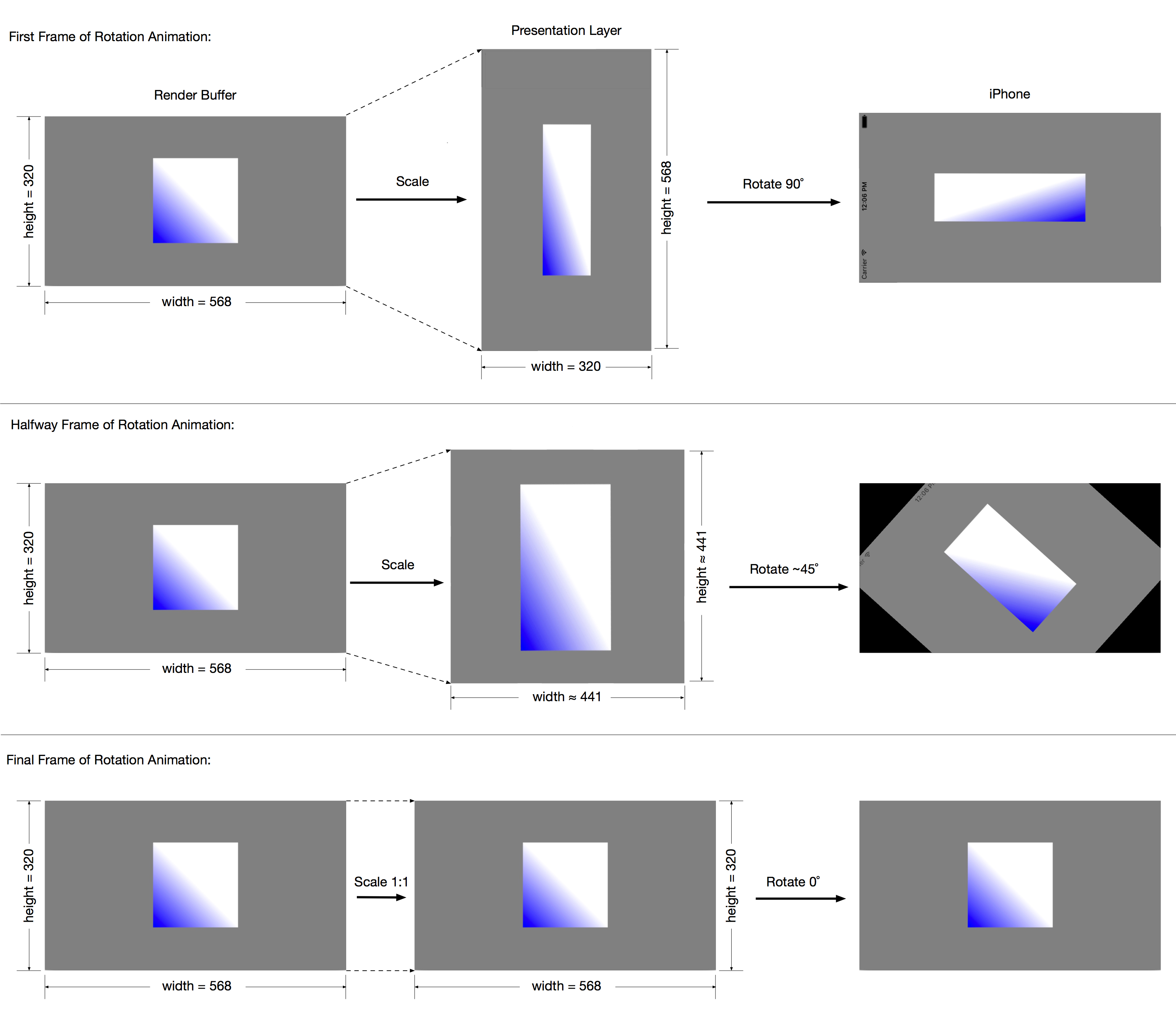
Let’s look at how the Presentation Layer changes during the transition. The diagram below shows the GL render buffer, the Presentation Layer, and the resulting iPhone display at the start, middle, and end of the rotation animation. At the beginning of the rotation, the GL buffer is the same width and height as the GL view on the iPhone; however, the Presentation Layer’s width and height are the exact opposite. Since the GL buffer is displayed in the Presentation Layer, a nonuniform scaling is applied, and the layer is rotated 90˚ to the GL view. At the end of the rotation animation, the scaling of the GL buffer into the Presentation Layer is 1:1, and no rotation need be applied. About halfway through, the Presentation Layer is a square whose edges’ lengths are halfway between the lengths of the long and short edges of the GL buffer, and the Presentation Layer is rotated 45˚.
Here’s a sequence of transitional sizes of the Presentation Layer during an orientation animation (apologies for jumping from sizes on an iPhone 5s to a 6s):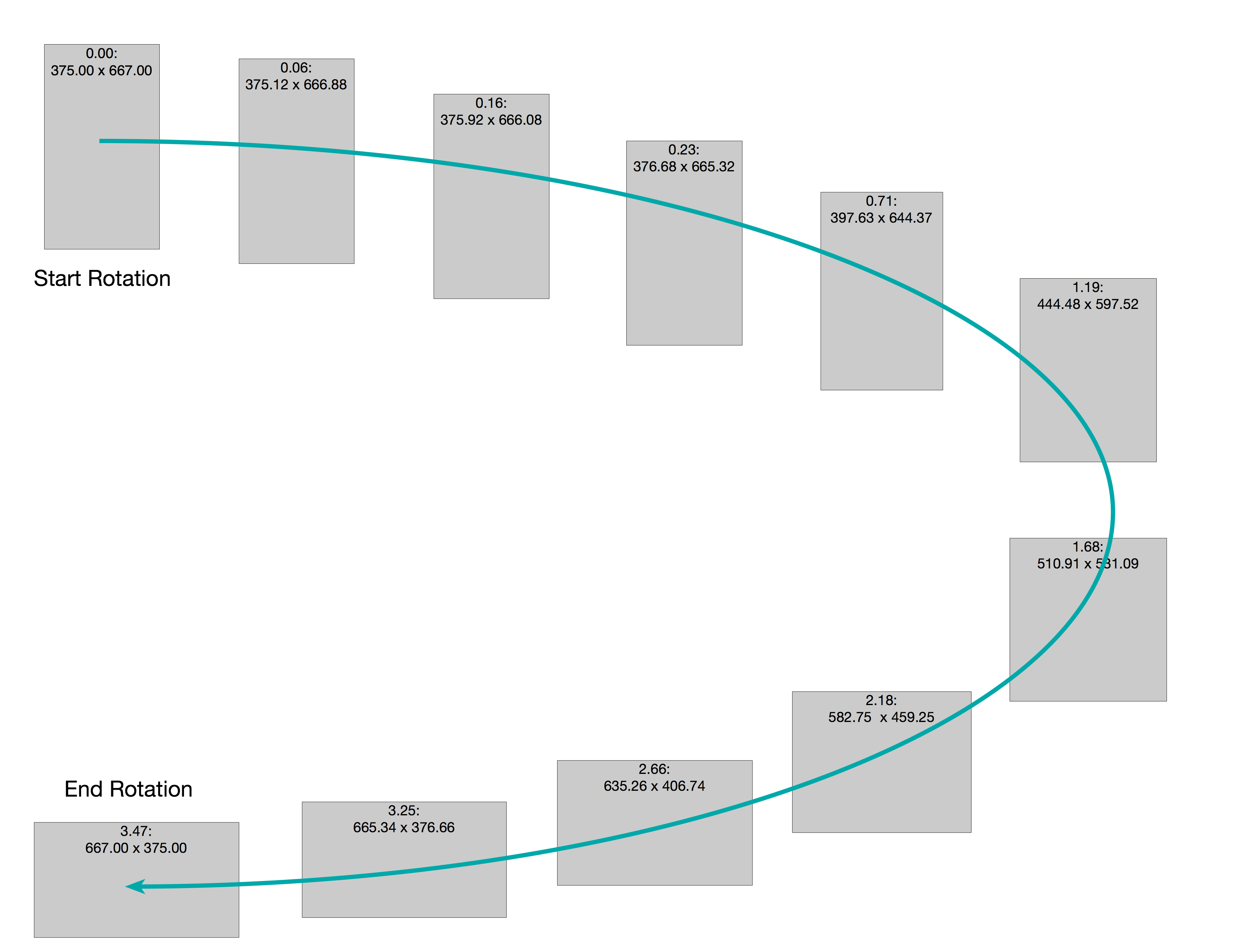
To make it more clear how the size and proportions are changing, I’ve graphed the width and height over time:
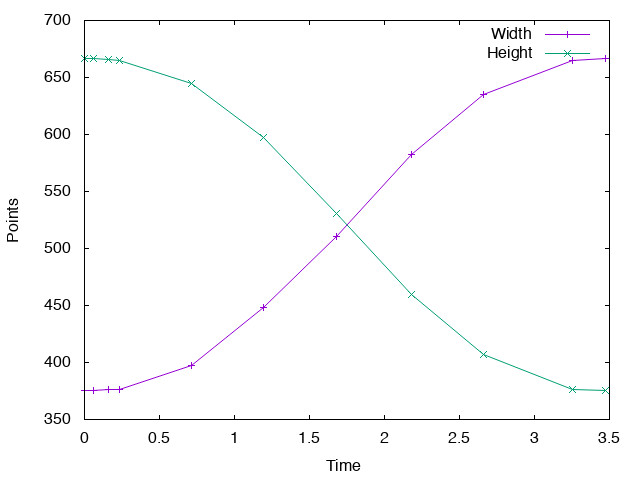
Note that the size and proportions don’t change linearly over time; rather, the graphs reflect a (typical) ease-in/ease-out animation curve for aesthetics.
So, What to Do?
An important issue to note here, in looking for a solution, is that UIKit provides you with enough information to know when an orientation has begun, and has ended. In this way, one can know when to apply one’s solution. Here’s the method in the sample code:
- (void)viewWillTransitionToSize:(CGSize)size
       withTransitionCoordinator:(id<UIViewControllerTransitionCoordinator>)coordinator
{
    [super viewWillTransitionToSize:size withTransitionCoordinator:coordinator];

    [self setTransitioning:YES];
    [coordinator animateAlongsideTransition:nil
                                 completion:^(id<UIViewControllerTransitionCoordinatorContext> context) {
                                     [self setTransitioning:NO];
                                 }];
}
Recall this is called right before the orientation animation begins, so I set up a BOOL property “transitioning” to YES. I can know when the orientation animation is finished by completion block for animateAlongsideTransition, where I set it back to NO. So, when I get the call to viewWillLayoutSubviews or render, I can apply my solution for the distortion during the transition, or just use the “normal” code path otherwise.
Earlier, I showed that the cause of the distortion during the rotation animation is due to nonuniform scaling of the GL buffer to fit into the Presentation Layer. So, what’s necessary is to modify one of the various OpenGL vertex transformation steps, such that we “invert” that scaling. The method I use is to modify the projection transform,
To get the desired results, one must first decide on the semantics of what one’s scene should look like in portrait, in landscape, and during the orientation transition. This is entirely application-dependent, so the precise details of my solution may not be what your application should do. But, armed with an understanding of what’s going on during the rotation animation, you should be able to come up with your application-specific solution.
Recall that my desired semantics are that my square should be half the size of the smallest GLView (or screen) dimension, in both device orientations. For the transition, let’s say I want those same semantics. To compensate for the “mismatch” between my render buffer and Presentation Layer sizes, I want to squash or stretch my left/right and width/height projection matrix parameters.
In my render() method, I know the sizes of both the GLView (render buffer) and the Presentation Layer. If I set the projection matrix parameters to match the size/proportions of the Presentation Layer, during the transition I’ll get a square that’s undistorted, and is always half the size of the smaller of the width and height of the Presentation Layer:
- (void)render:(CADisplayLink *)displayLink
{
    GLView *glView = (GLView *)[self view];

    // Set the viewport
    glViewport(0, 0, [glView bounds].size.width, [glView bounds].size.height);

    // Compute the projection matrix
    GLKMatrix4 projectionMatrix;

    if ([self isTransitioning]) {
        CGSize  presentationLayerBoundsSize = [[[[self view] layer] presentationLayer] bounds].size;
        CGFloat presentationLayerRatio      = presentationLayerBoundsSize.width / presentationLayerBoundsSize.height;
        GlFloat ratio                       = presentationLayerRatio;
        if (ratio <= 1)
            projectionMatrix = GLKMatrix4MakeOrtho(-1, 1, -1/ratio, 1/ratio, 0, 100);
        else
            projectionMatrix = GLKMatrix4MakeOrtho(-ratio, ratio, -1, 1, 0, 100);
    }
    else {
        // Non-transition projection matrix.
        GLfloat ratio = [glView bounds].size.width/[glView bounds].size.height;
        if (ratio <= 1)
            projectionMatrix = GLKMatrix4MakeOrtho(-1, 1, -1/ratio, 1/ratio, 0, 100);
        else
            projectionMatrix = GLKMatrix4MakeOrtho(-ratio, ratio, -1, 1, 0, 100);
    }

    // Set projection matrix
    glUniformMatrix4fv([self projectionLocation], 1, 0, (const float *)&projectionMatrix);
    ...
}
The result is an undistorted rotation animation (the square remains a square), as we can see in this video:
HQ Version: Undistorted Rotation
The reason this works is that I’ve “undone” the distortion due to the mismatch between the GLView and the Presentation Layer by exactly compensating for the nonuniform scaling using the projection transformation — I’ve “lied” about where the corners of the canonical view volume are located.
A Slight Improvement
Well, this is a lot better than the stretchy square we had originally, but during the transition, our square gets larger, and then progressively smaller. The reason is that halfway through the orientation transition, the Presentation Layer is a square, whose sides are larger than the smaller of the two dimensions at the end of the transition, so of course the rendered square is larger.
Depending on the intended semantics of your transition, this may or may not be what you wanted. In my case, this still looked a little wrong. What I want is the square to remain the same size on screen, all throughout the transition. Since I want the square to remain a square, I need to use the same technique I’ve been using. But, I need to apply a nonuniform scale to the projection matrix, and the scale needs to take into account the dimensions of the Presentation Layer relative to the GL view. The solution here is to use the ratio of the GL view’s width and height to the presentation layer’s width and height, respectively, for the scaling in x and y:
- (void)render:(CADisplayLink *)displayLink
{
    GLView *glView = (GLView *)[self view];

    // Set the viewport
    glViewport(0, 0, [glView bounds].size.width, [glView bounds].size.height);

    // Compute the projection matrix
    GLKMatrix4 projectionMatrix;
    GLfloat    ratio = [glView bounds].size.width/[glView bounds].size.height;

    if ([self isTransitioning]) {
        // Set the projection to match the dimensions of the GL view.
        if (ratio <= 1) {
            projectionMatrix = GLKMatrix4MakeOrtho(-1, 1, -1/ratio, 1/ratio, 0, 100);
        }
        else {
            projectionMatrix = GLKMatrix4MakeOrtho(-ratio, ratio, -1, 1, 0, 100);
        }

        // Adjust the projection matrix to keep a constant size of displayed
        // square.
        CGSize     presentationLayerBoundsSize = [[[[self view] layer] presentationLayer] bounds].size;
        GLfloat    widthRatio                  = [glView bounds].size.width  / presentationLayerBoundsSize.width;
        GLfloat    heightRatio                 = [glView bounds].size.height / presentationLayerBoundsSize.height;
        GLKMatrix4 scaleMatrix                 = GLKMatrix4MakeScale(widthRatio, heightRatio, 1);

        projectionMatrix = GLKMatrix4Multiply(projectionMatrix, scaleMatrix);
    }
    else {
        // Non-transition projection matrix.
        if (ratio <= 1) {
            projectionMatrix = GLKMatrix4MakeOrtho(-1, 1, -1/ratio, 1/ratio, 0, 100);
        }
        else {
            projectionMatrix = GLKMatrix4MakeOrtho(-ratio, ratio, -1, 1, 0, 100);
        }
    }

    // Set projection matrix
    glUniformMatrix4fv([self projectionLocation], 1, 0, (const float *)&projectionMatrix);

    ...
}
This is the result:
HQ Version: Constant Size Rotation
Conclusion
In spite of the rather lengthy explanation I’ve given, the basic issue with handling OpenGL display during device rotation is simply that the system displays your view’s contents indirectly via a Presentation Layer that changes size/shape during the transition animation. Solving the problem involves compensating, in one way or another, for this behavior. In my (overly) simple sample code, I’ve defined what my scene should look like before, during, and after a device orientation change, and used the projection transform to compensate for the Presentation Layer’s disparity with my render buffer’s proportions.